Week 14: Interface and application programming
The assignment:
1. Group assignemt: LINK to the group assignment
2. Individual assignment:Write an application that interfaces a user with an input &/or output device that you made.
In class we learned how to send and receive data using the software: LINK to software: Processing We learned about it using both serial and networked communication. I focused on serial communication and first I did the exercise that we also did in class (touching a square on the computerscreen with the mouse that then activated the LED on the Barduino.) The assignment of this week is about doing something similar - only with my own board. Unfortunately I experienced problems with my board – I couldn´t upload anything to it ("UPDI initialisation failed") – so below I will explain the code using the Barduino.
To make this happen we uploaded a code to the Barduino in order to make the serial connection and to activate the LED when data is received.
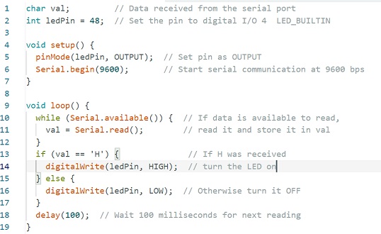
The LedPin is set to pin 48, because that is where the LED is on the Barduino. In void setup (runs only once) the baut rate is set to 9600 bits per second. This allows serial communication between the computer, the port and my board in a defined rate (the number can change). Under void loop (runs continously) I write if the received character is ‘H’, it turns on an LED; otherwise, it turns the LED off. The delay at the end controls the loop timing, because the data is read very fast and a delay slows things down a bit (unnoticable) – to avoid faults in the reading.
On the other side in the software “Processesing” - based on Java - the code for sending data is written
Under void setup you define the size of the square – size (200, 200) and the bautrate to 9600 to enable the serial communication Under void draw I can set the background colour (255 is back) and define that if the mouse hoovers over the square an H is send, - if not an L is send and as we saw in the Arduino code the LED goes on if an H is received.
This is an example of the result:
Using the serial plotter in ArduinoIDE and sending the data to Processing.
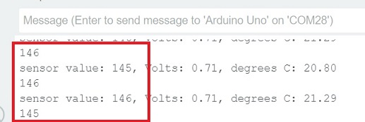
To understand how this works I had made a setup with an Arduino, breadboard and the components and code from the the examples>starterkit>Love-o-meter. In this example the code reads temperature and turns on some LEDs and gives the values of the sensor, the volts and a calculation of the temperature.
To write the values to the serial plotter in ArduinoIDE I added this code:
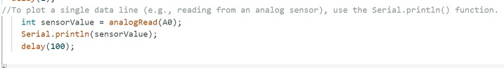
Now the the plotter showed the sensor value.
To log this I used Processing. Here I wrote this:
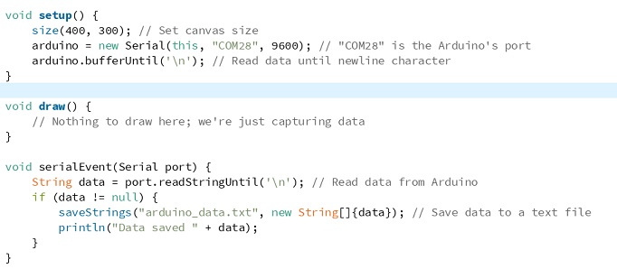
This created a txt-file with the sensor value
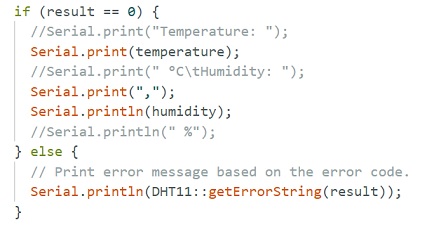
Now I tried with my own board. I had trouble getting the code right for displaying temperature and moisture in the serial plotter. But in the end, after consulting an instructor; I added this to the sketch:
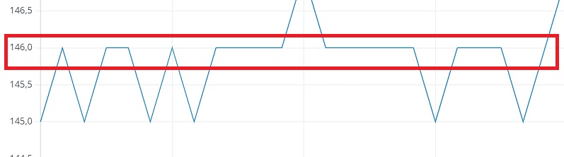
The serial plotter now displayed this:
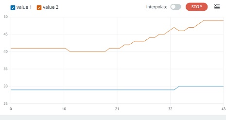
Value 1, the blue line = temperature and Value 2, the red line = humidity. Now I had something to test in processing. I used the same code as in the exercise above, - only changing the port to 23.
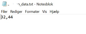
The values were saved as a *.txt file, when I stopped the processing from running:
Publish sensor readings from ESP32 and the DHT11 to Google Sheets using IFTTT.
During the week I was pointed in the direction of https://ifttt.com/. What I wanted to do was to publish sensor readings from ESP32 and the DHT11 to Google Sheets using IFTTT. I already had the board up and running and could read moisture and temperature in the serial monitor in Arduino IDE. I now needed the IFTTT part
To set up IFTTT I did this:
The coding part in Arduino IDE
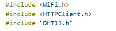
First I setup the wifi connection, http client and the sensor
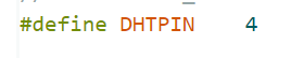
Then I defined the pin number to the DHT11
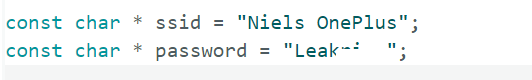
The the credentials for the network
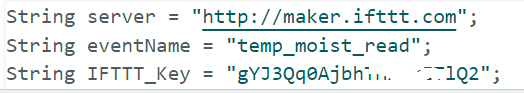
And the servername, the name of my event and the key
The full original file is here.
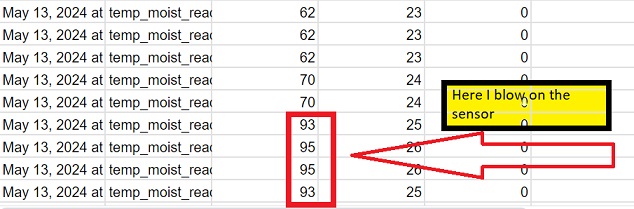
See the reading in the Google spreadsheet here